Welcome to episode eight of our Let’s Remake Manic Miner series. In this episode, we are going to look at how we can add some collision detection to Miner Willy. This episode is going to be super long, so it will be split into multiple parts. In part one, we will discuss the concept of collision detection and how we can deal with it in STOS.
What is collision detection?
Collision detection is the computational problem of detecting the intersection of two or more objects.
Wikipedia
Ok, now that we’ve cleared that up, we can crack on… what? explain it a little more? Alright then!
When we’re talking about computer games, what it is basically saying is: How can we tell if one object in our program is overlapping (intersecting) another object in our program? In other words, colliding with each other. In our instance, objects are the different game elements, such as walls, nasties, guardians, and Miner Willy himself.
When you’re dealing with game sprites, there are various ways this can be done, and there are varying terms such as collision masks, bounding boxes, and hitboxes. I’m not going to deal with any of these elements as part of this series, so please read up on those independently. We’re going to simplify things just as Matthew Smith did with Manic Miner and check various points around our Miner Willy character to determine what he is up against. I guess you could call these hitboxes, albeit very small ones.
Hotspots
Before we look at the points at which we are going to calculate collisions, let’s have a quick discussion about hotspots. Firstly, what is a hotspot? A sprite hotspot is a point on a sprite image that defines its origin or centre of rotation. It is specified by a pair of coordinates relative to the top-left corner of the sprite. For example, a sprite hotspot of (0,0) means that the top-left pixel of the sprite is its origin, while a sprite hotspot of (16,16) means that the pixel at 16 pixels from the left and 16 pixels from the top is its origin. Sprite hotspots are useful for positioning and transforming sprites on the screen, such as moving, scaling, rotating, or flipping them.
STOS provides a hotspot for its sprites, which denotes the 0,0 origin of the sprite. That is to say, if you displayed the sprite at 0,0, the hotspot is the part of the sprite that would be shown at 0,0. We can edit the hotspot of a sprite using this STOS sprite editor.
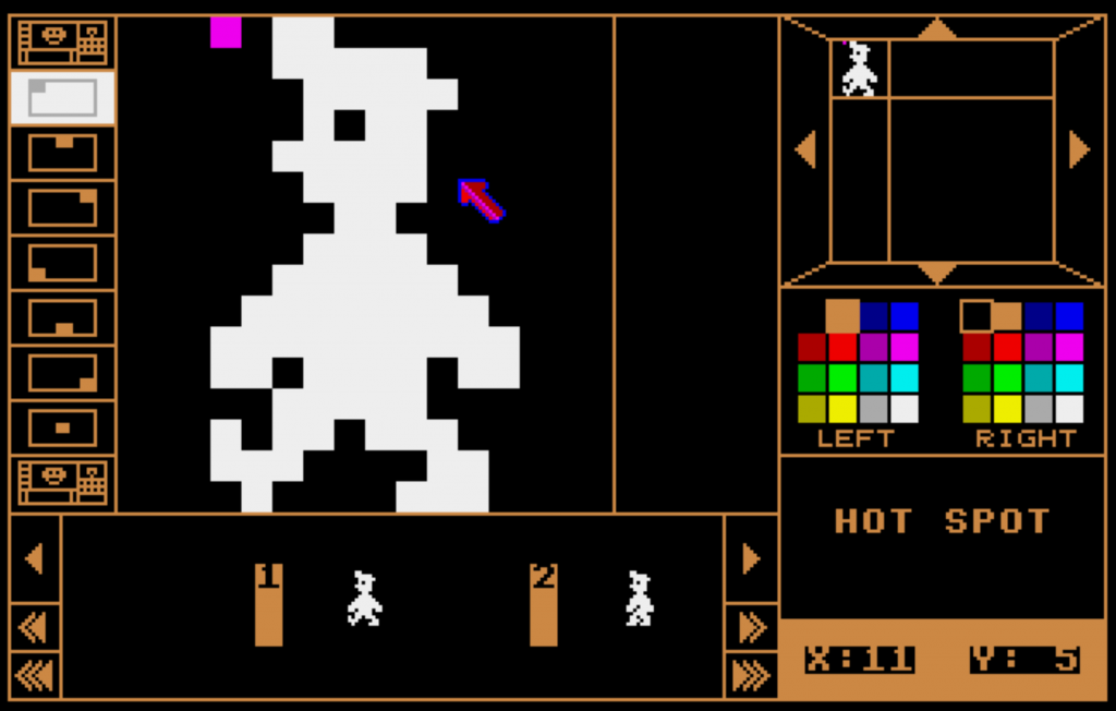
The purple square at the top left of the Miner Willy image denotes the existing hotspot. You can see with the options on the left-hand side that STOS offers a number of defaults that can be applied to your sprite. You can have a different hotspot per animation frame, which makes using the STOS collision routines easier to work with.
Our hotspot is currently at xposition 3, and yposition 0. If we were to place our sprite on the STOS screen at 0,0, it is this position that would be shown there, meaning that the top left of our sprite is actually being displayed at -3,0.
Collisions using hotspots
STOS only caters for the use of a single hotspot for it’s collision detection, and it uses a rectangular hitbox with a defined width and height. This is performed using the COLLIDE command that is available to us. However, it only detects collisions between sprites. Because of the way we are writing Manic Miner, the only sprites we will have on screen will be the guardians, as they are the only moving elements; everything else is static. We may revisit that statement later in the series when we look at the conveyor belts, but for the moment, let’s stick to it! We can’t therefore use the standard STOS COLLIDE command for this, so we will need to come up with a different way of doing it.
You can find more information about the STOS collision detection on page 94 of the STOS user manual.
Irregular-shape collision
We could look at using the DETECT command within STOS to allow us to detect the pixel colour that is under our hotspot and then execute our collision code depending on what we find. This method has merit; however, it has a number of drawbacks. Firstly, the DETECT command is ridiculously slow! Do we even need to discuss other drawbacks now? There is, for me, an even bigger drawback. It will literally grab the colour of the pixel under the hotspot. So if your game has some form of background or map, then that is going to be returned if your sprite is over it. It would have been a much better command if you could specify a different memory area other than the main screen. That’s where The Missing Link / Misty extension POINT command comes in handy because you can make an image-based collision map as a separate screen image and read data from that.
You can find more information about the STOS DETECT command on page 97 of the user manual.
Collision maps
For Manic Miner, we’re going to use the concept of a collision map, but what is that? Collision maps can come in two forms, but they essentially perform the same task; they represent shapes that will be used for collision checking. Let’s generate both types of collision maps for the Central Cavern level.
This is what our level looks like without the sprites on it.
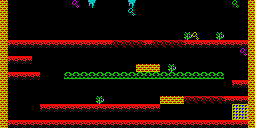
Image-based collision map
The first type of collision map is an image-based one. This means that an image is used to define the collision rules for areas of the screen. This is where The Missing Link / Misty extension POINT command would be used. To convert the above map into an image-based collision map, we simply replace the coloured elements of the map with something that means something to us. For example, we set all the walls to colour 1, all the floors to colour 2, etc. That way, when the POINT command is used, we know how to deal with the returned value that we get.
This is an example of how our image may look after we have done that conversion. I’ve added a dark blue border to highlight the white sides of the image.
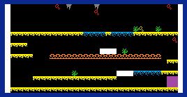
What we can see here is that we have removed all colour detail from the image. Sure, it’s only the yellow and red of the bricks and the detail from the portal, but hopefully you get the idea. What we could now do is use this image for reading points under Miner Willy and then, depending on the colour we get back, act appropriately. For example, if Miner Willy hits a yellow pixel, we know that he’s hit the floor and can therefore stop falling. If he hits a green pixel, we know he has collided with the cactus, which will make him lose his life.
Tile-based collision map
So what’s the difference between an image-based collision map and a tile-based collision map? Rather than using a picture and colours, we reference a table that holds the number of the map tile that is under our character. We can then use that to decide how Miner Willy reacts. For example, if he hits a wall tile, we can stop him from walking.
There are commands in The Missing Link / Misty that deal with what tile is at what coordinates within its WORLD command mapping functions. But, alas, we are using raw STOS, and this is not an option for us.
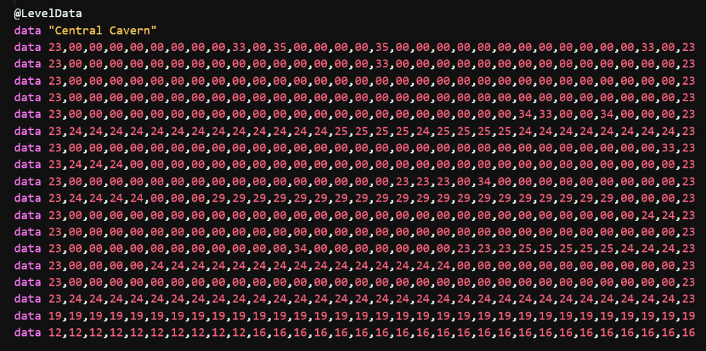
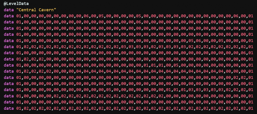
You’ll remember from episode 6 where we actually built our level, and we used data statements to hold which tiles to show where on the map. Well, that’s our tile map, and it’s the method we are going to use for our game.
But what we are going to do is simplify it so that we don’t have to keep checking loads and loads of different values all the time – the fewer IF/THEN statements we need to do, the better. Wouldn’t it be wonderful if STOS had a case statement? Sigh.
What we will do is simplify the map to identifiable elements rather than sprite numbers. Much like we did with the colours, but this time identifying the type of tile that is at the coordinate. Each level in Manic Miner has eight different tile elements that can be used within the screen, so this means we can really simplify our collision map. Happy days!
| # | Description |
| 0 | Represents a transparent area on the screen. So where we see a zero, it means there is no tile present. |
| 1 | Represents a solid wall tile that Miner Willy cannot walk or jump through |
| 2 | Represents a standard, solid floor tile that Miner Willy stands on. He can jump through it, but he cannot fall through it. |
| 3 | Represents a crumbling floor tile. These are the tiles that slowly disappear the longer that Miner Willy stands on them. |
| 4 | Represents a conveyor belt. When Miner Willy stands on one of these tiles, he will automatically move in the direction that the belt is rotating. |
| 5 | Represents a nasty such as a cactus. When Miner Willy hits these, he will lose a life. |
| 6 | Represents a collectable item, such as a key. |
| 7 | An actionable object, such as the switches that are used in later levels of the game. |
So all we need to do is transpose the data we created in episode six into the tile representations above. Let’s add the tile map to our source code and read it into memory, ready for usage.
We’ll modify our @NewGame function so that we’re not constantly loading and reading the level information. We’ll add a new @InitLevel function so that we can handle the loading of the image and the reading of the map data.
@NewGame
    LVL = 1 : LIVES = 3 : GAMEOVER = false
    gosub @InitLevel

    // Level loop
    repeat
        gosub @InitMinerWilly
        LVLDONE = false : MWDEAD = false

        // Gameplay loop
        repeat
            gosub @ReadJoystick
            gosub @DisplayMinerWilly
            gosub @WaitVBL
        until LVLDON or MWDEAD

        if MWDEAD then dec LIVES : GAMEOVER = (LIVES = 0)
        if LVLDONE then inc LVL : gosub @InitLevel
    until GAMEOVER
    return

@InitLevel
    LVL$ = str$(LVL) - " " : if len(LVL$) = 1 then LVL$ = "0" + LVL$
    load "LEVEL" + LVL$ + ".PI1",10
    screen copy 10 to physic : screen copy 10 to back
    return
Now let’s add the relevant code to read the tile map into memory from the data statements.
Firstly, at the beginning of the code, we will define some room for the tilemap. We’ll do this using an array.
erase 10 : reserve as screen 10

// Create some memory for the tile map data (32x16 tiles)
dim map(511)

gosub @LoadAssets
Could we create a bigger array? For sure, we could create an array that represents each x and y pixel on the screen to hold what tile is at that pixel to save having to convert to tile position, thus saving CPU time. But that takes memory (it would take 64k in fact), and we want to keep this game as lean as possible. So we are going to have to sacrifice a little speed for memory.
Add the following code to the @InitLevel function
@InitLevel
    restore
    read LVLNAME$

    for t = 0 to 511
        read TNO
        map(t) = TNO
    next t

    LVL$ = str$(LVL) - " " : if len(LVL$) = 1 then LVL$ = "0" + LVL$
    load "LEVEL" + LVL$ + ".PI1",10
    screen copy 10 to physic : screen copy 10 to back

    return
Here we are simply reading the tile number in one large stream. We need to remember that there are 32 tiles going across the screen and 16 tiles going down.
I think that is probably enough for this part of episode 8. In the next episode, we will use the map data and add the code necessary to stop Miner Willy from walking through walls.
Until then… Happy STOSing.
[…] you haven’t already checked out part 1 of Episode 8, make sure you read through it to understand some of the code that we have in […]